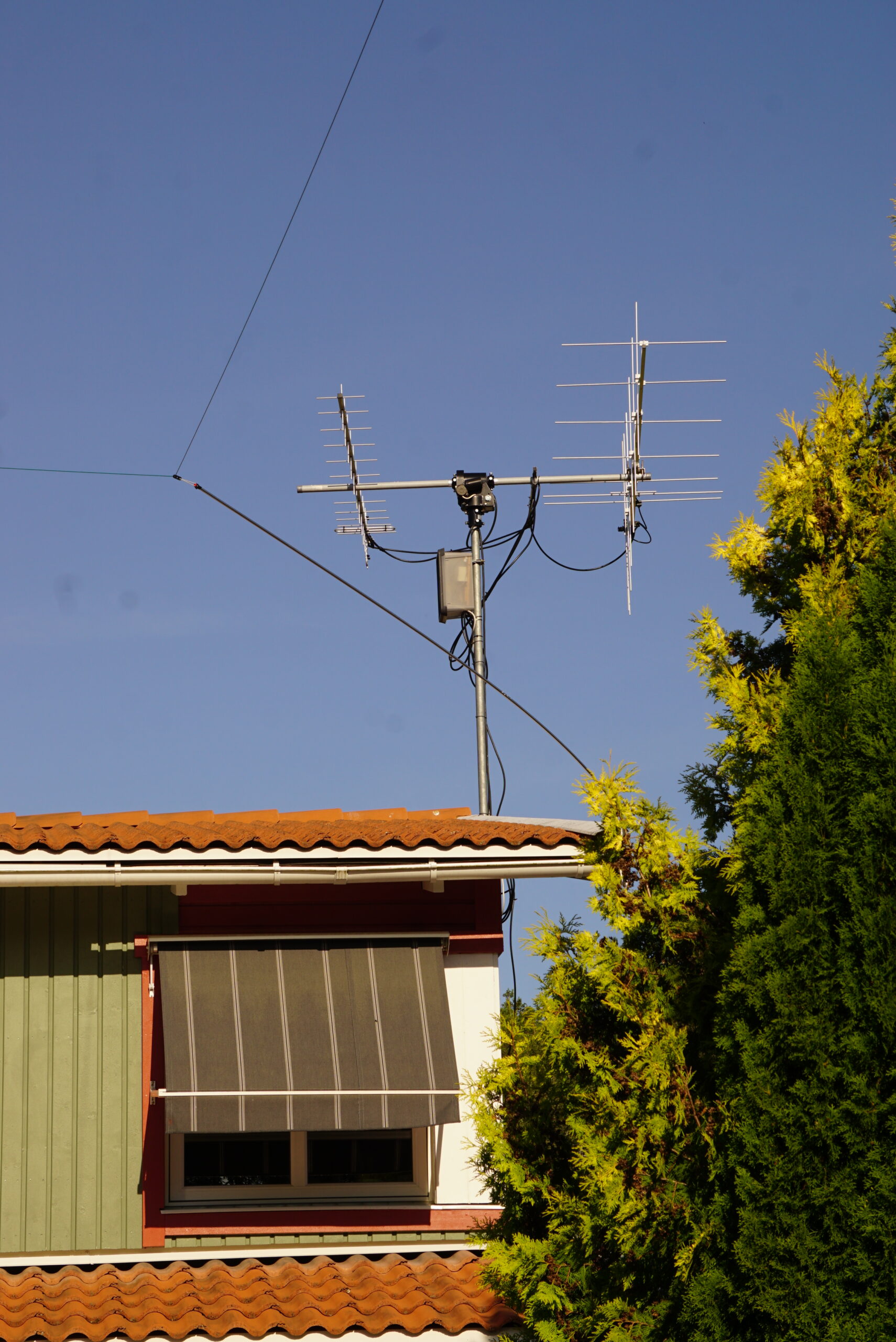
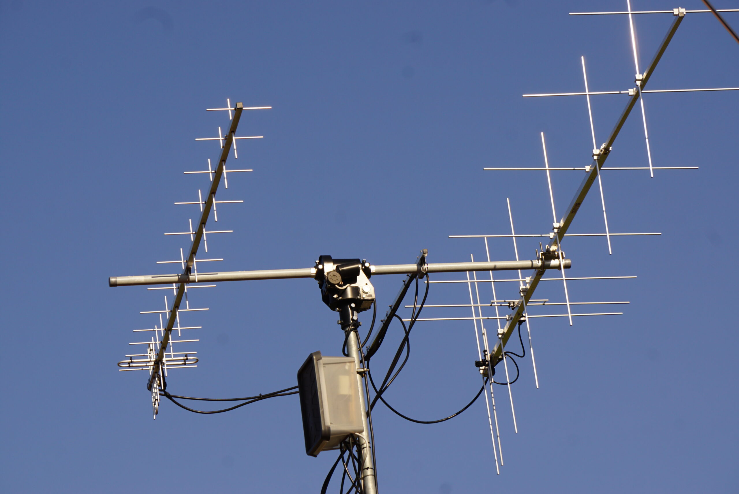
Some time ago now – but I made two EME QSOs with DL7APV (now SK) in February 2023. I used my 2* 15 el LFA X-yagi and 40 watt output from IC-9700.
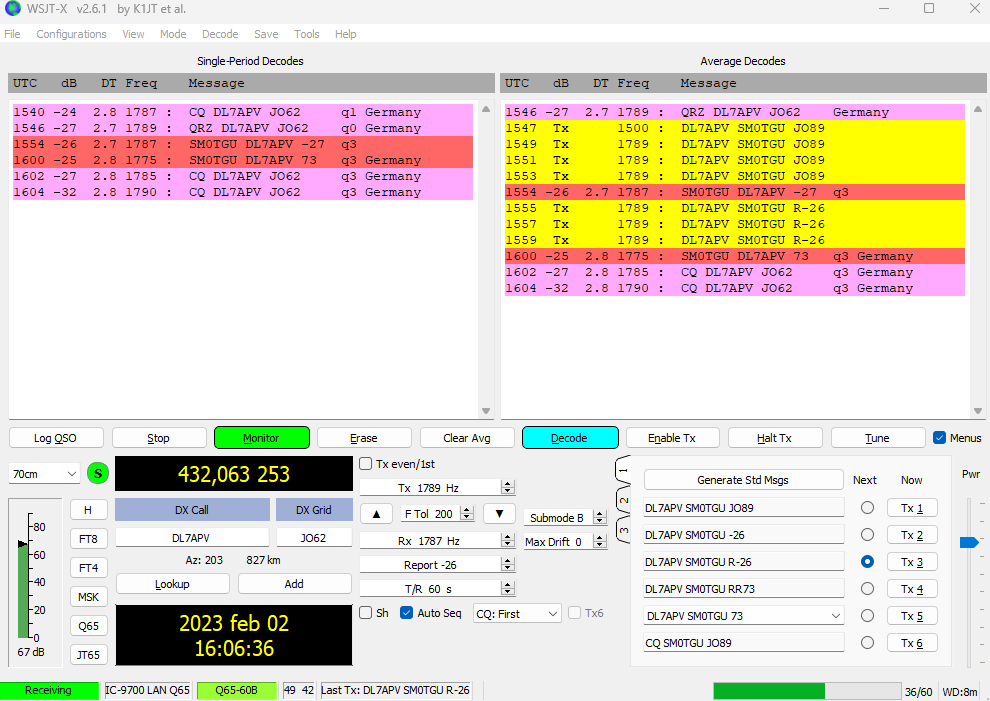
See also my Tweet from this event:
Blogs and posts about my amateur radio and satellite projects. Most posts are in english.
Some time ago now – but I made two EME QSOs with DL7APV (now SK) in February 2023. I used my 2* 15 el LFA X-yagi and 40 watt output from IC-9700.
See also my Tweet from this event:
Trying to receive #eme but hear nothing…. pic.twitter.com/PaPrt1dvha
— AMSAT-SM (SM0TGU Lars) (@amsat_sm) February 2, 2023
Some test with the internal LNA (P.AMP) of the IC-9700 and external LNA. What combinations will give the best SNR? Note that all tests are done without any type of professional equipment – only by looking at the waterfall and listening with my ears.
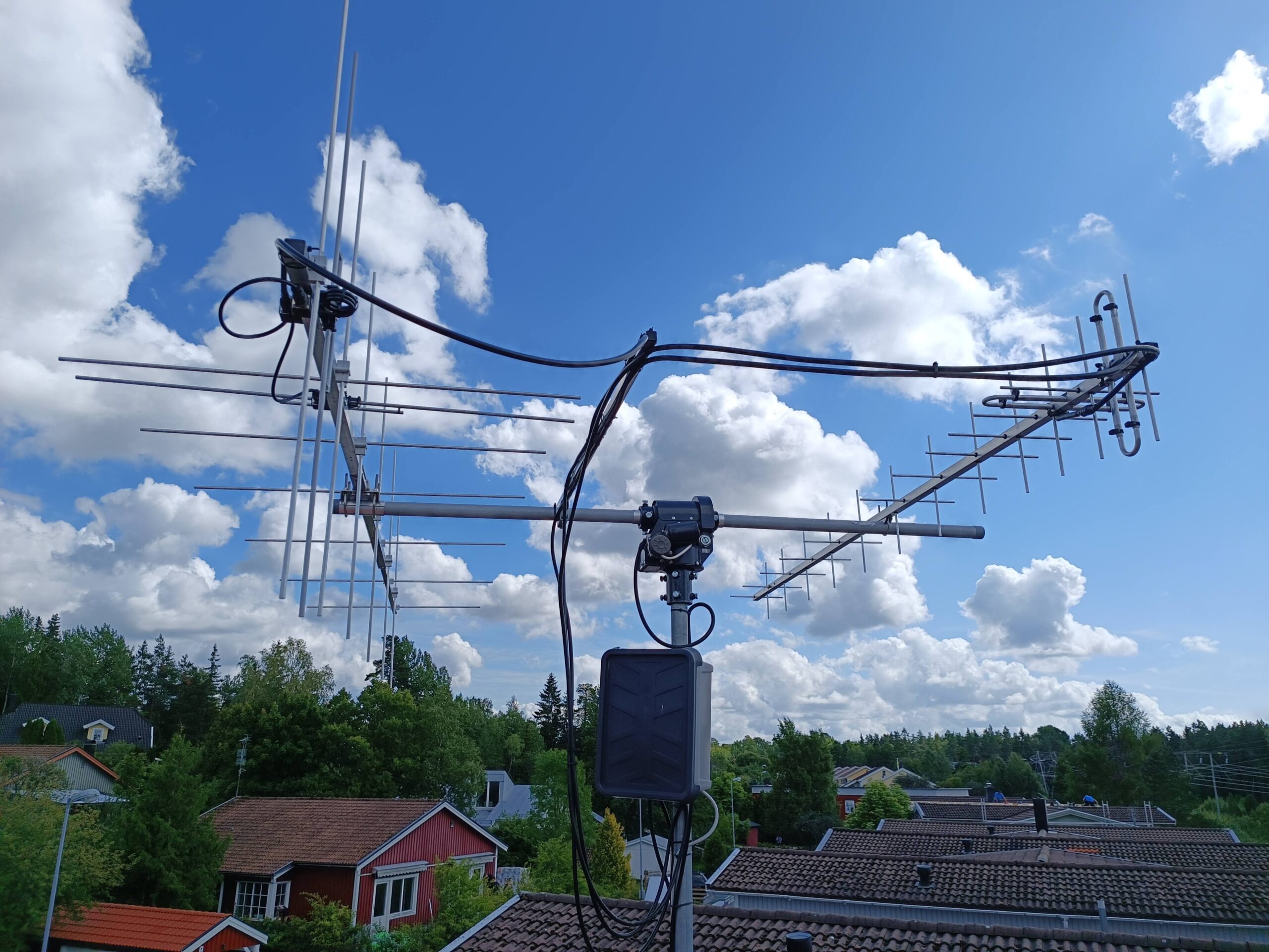
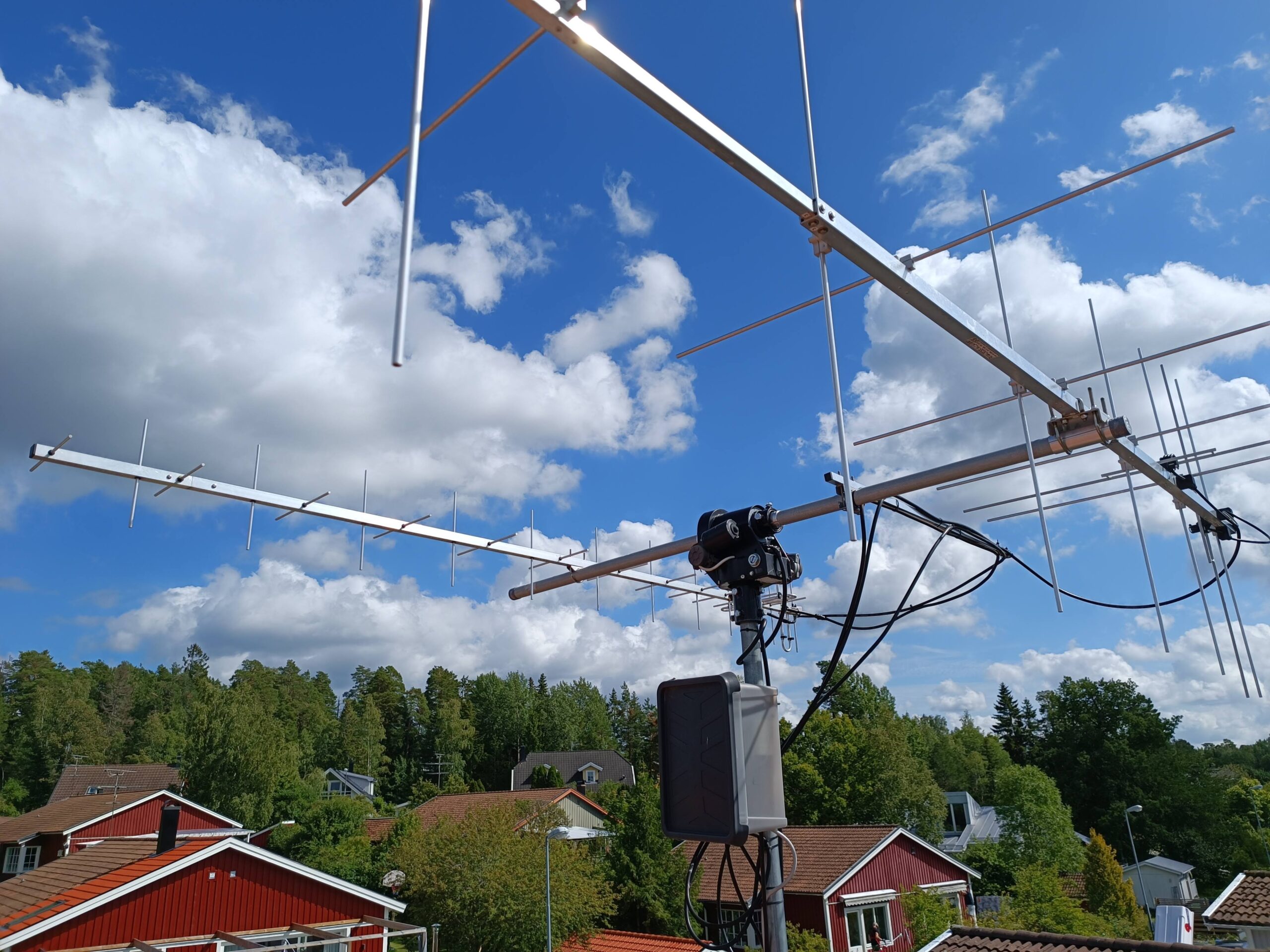
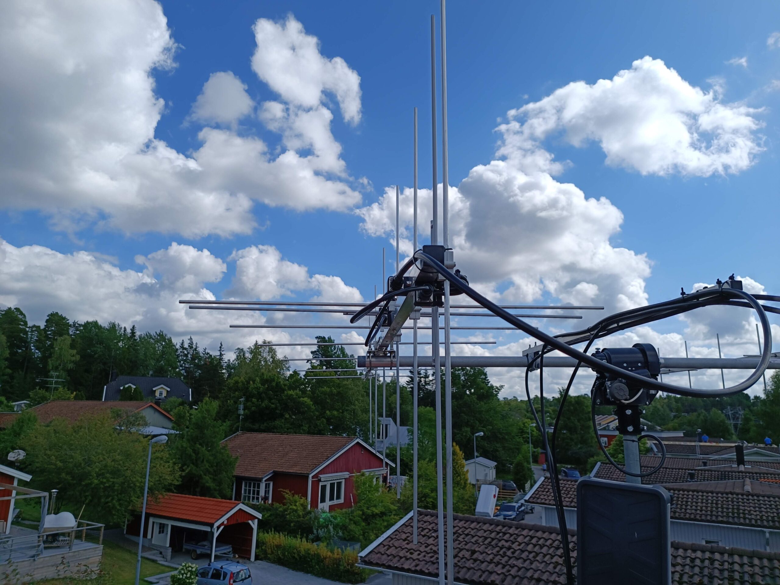
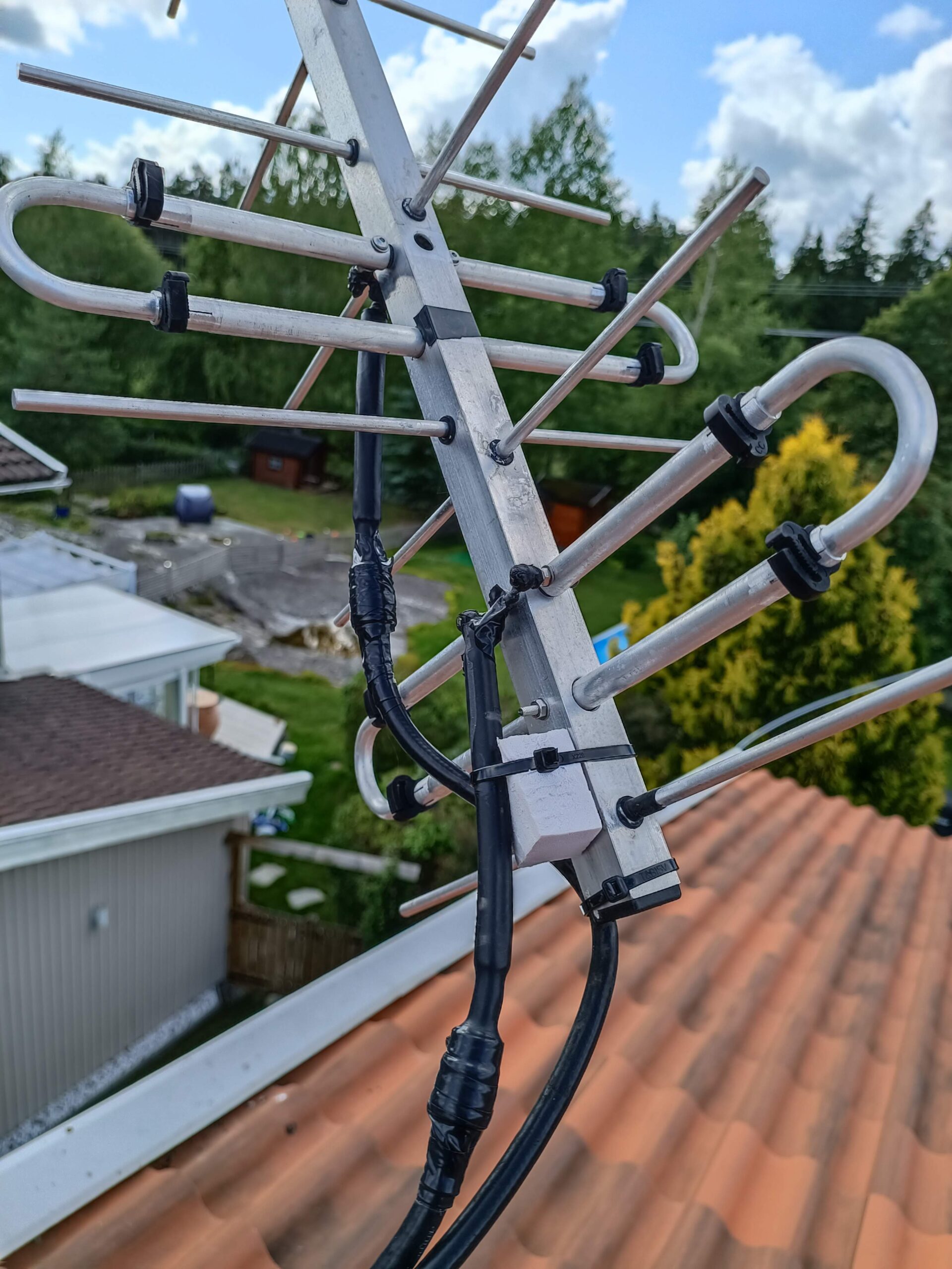
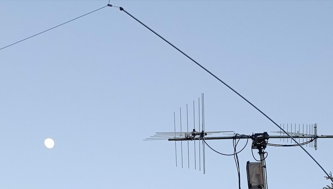
I have used my VHF and UHF yagis and external LNAs Mini-2 and Mini-70 mounted just below the antennas. I have aprox. 16 meters of high quality LMR-400 cables between the IC-9700 and antennas/LNAs.
VHF – beacon SK1VHF at 144.447 MHz
| Without internal P.AMP and external LNA | Not possible to hear beacon |
| With only internal P.AMP | Possible to hear beacon |
| With both internal P.AMP and external LNA | Better SNR but needed to reduce RFGain to get good SNR |
| With only external LNA | Best SNR! No need to reduce RFGain. |
Note on VHF: The difference between using both internal P.AMP + external LNA and only external LNA is not huge, but is clearly audible.
UHF – beacon SK1UHF at 432.405 MHz
| Without internal P.AMP and external LNA | Not possible to hear beacon |
| With only internal P.AMP | Possible to hear beacon |
| With both internal P.AMP and external LNA | Better SNR but needed to reduce RFGain to get good SNR |
| With only external LNA | Best SNR! No need to reduce RFGain. |
Note on UHF: Almost the same result as VHF, but the external LNA gives better result and SNR compared to VHF.
Summary:
If you do not have an external LNA it is mandatory to use the internal P.AMP on the IC-9700 for very weak signals.
If you have a good external LNA mounted close to the antenna it is best to turn off the internal P.AMP to get best SNR.
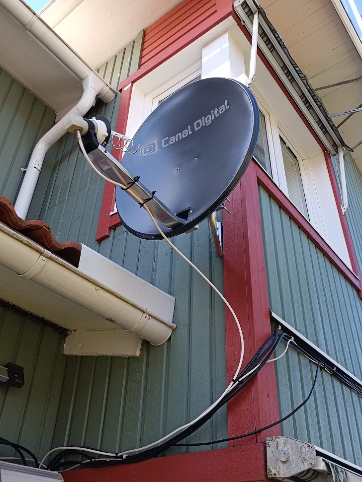
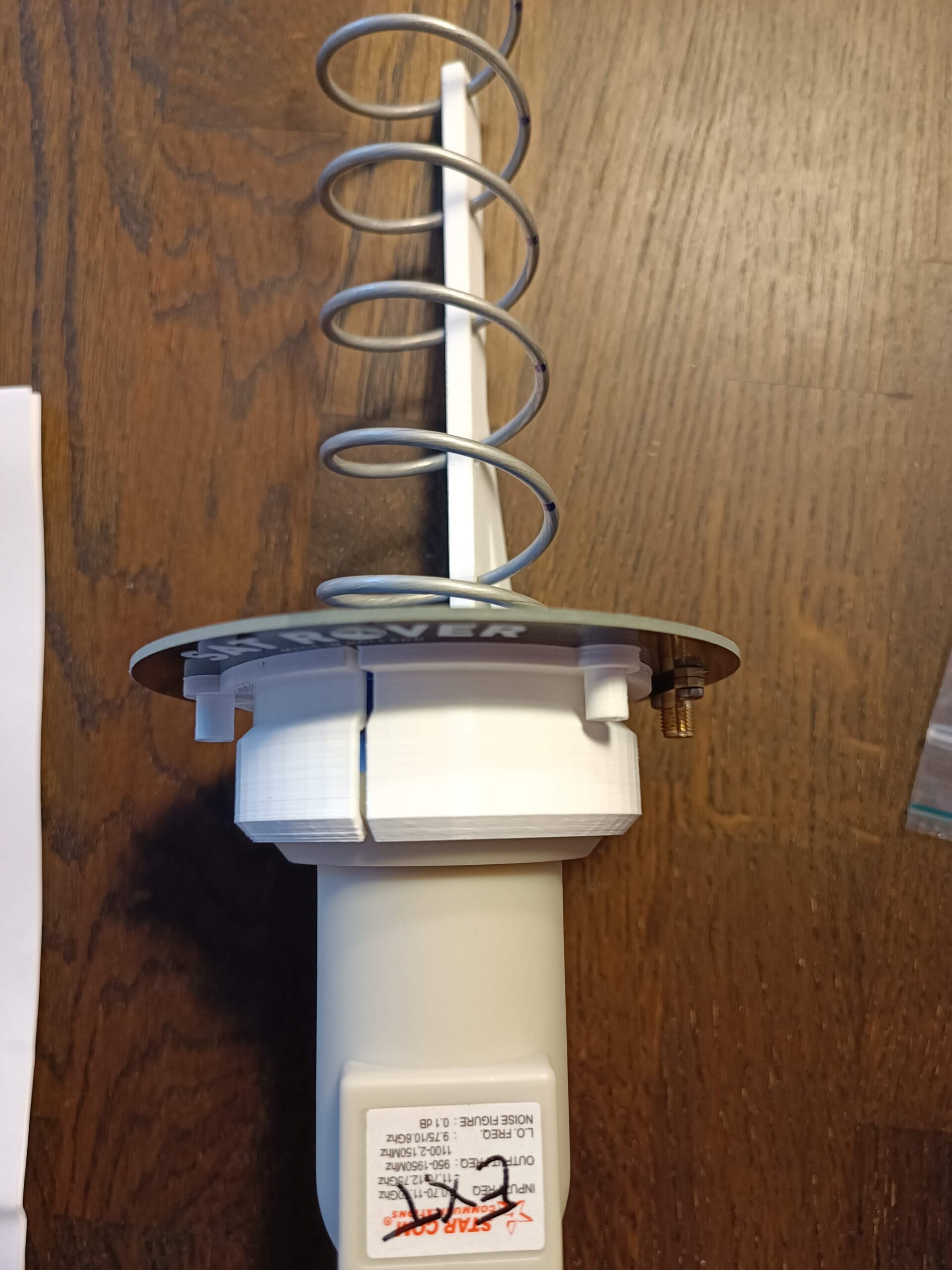
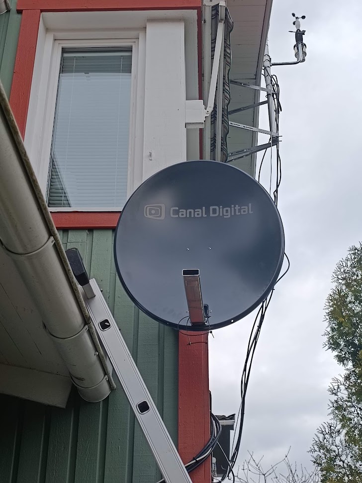
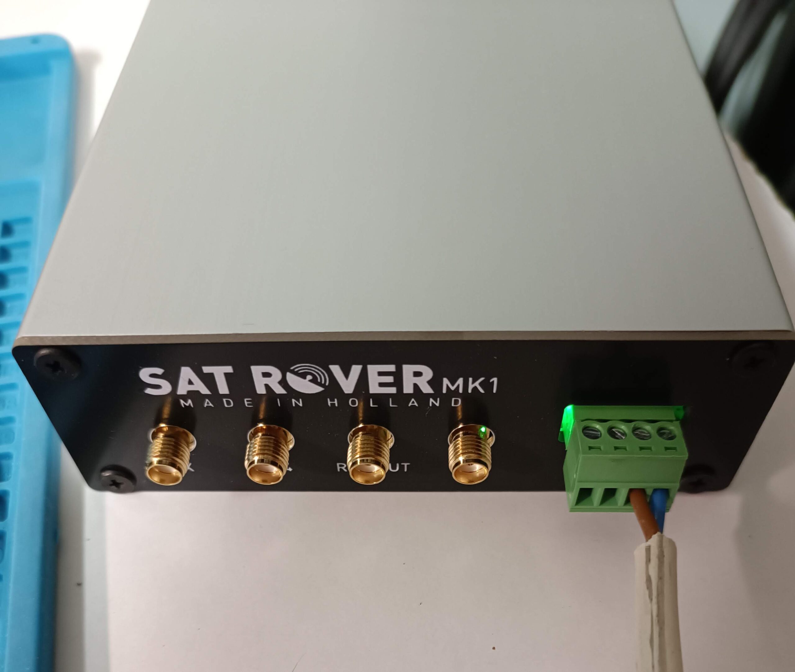
This is my final QO-100 fixed setup with the SatRover:
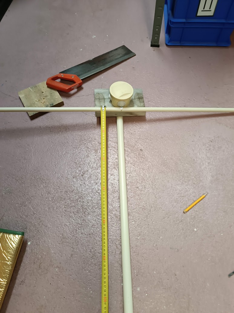
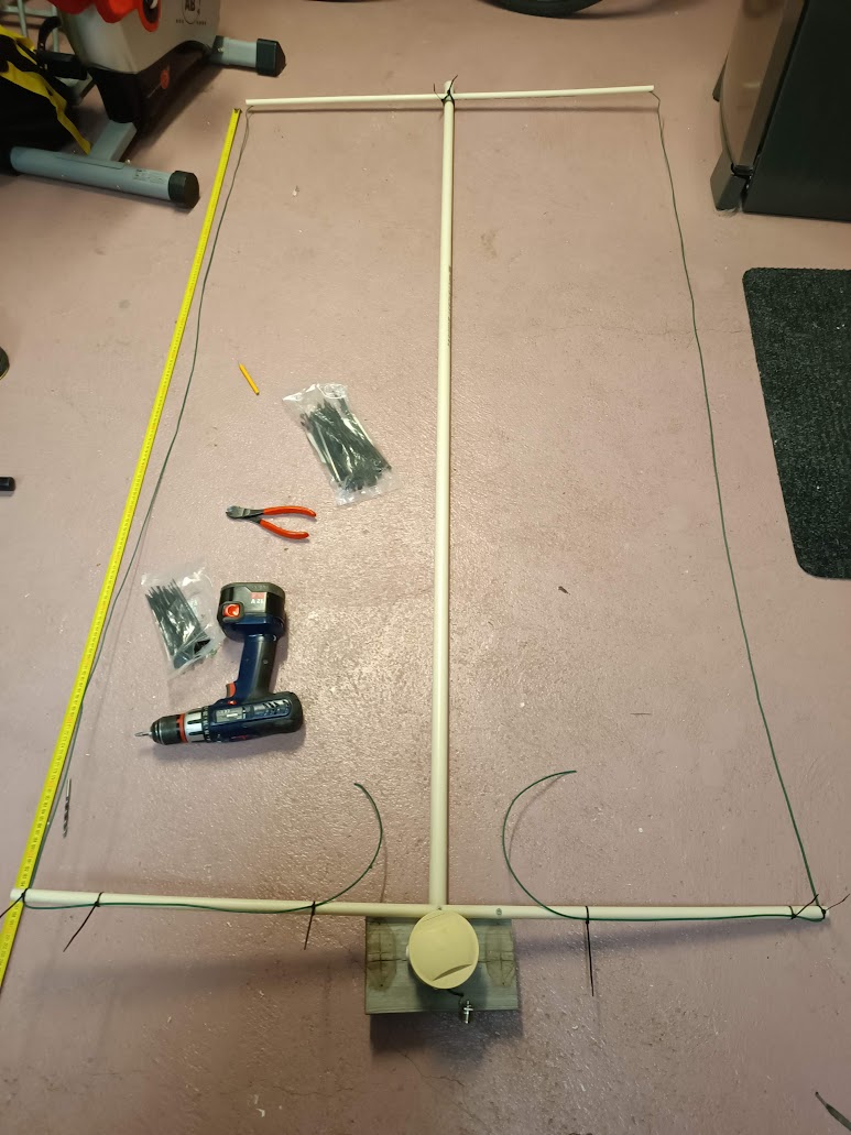
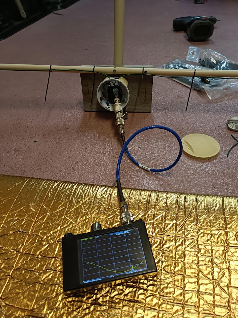
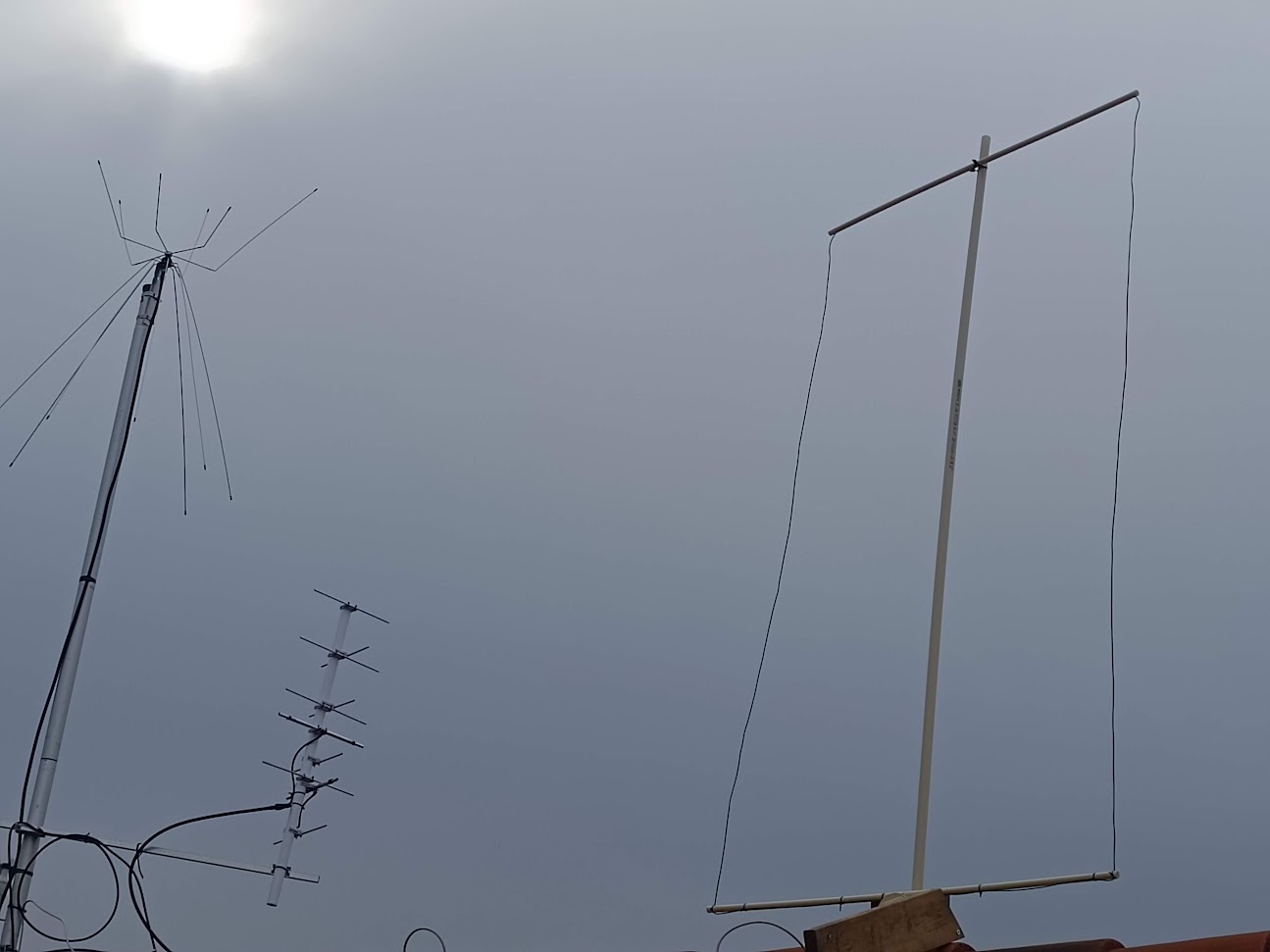
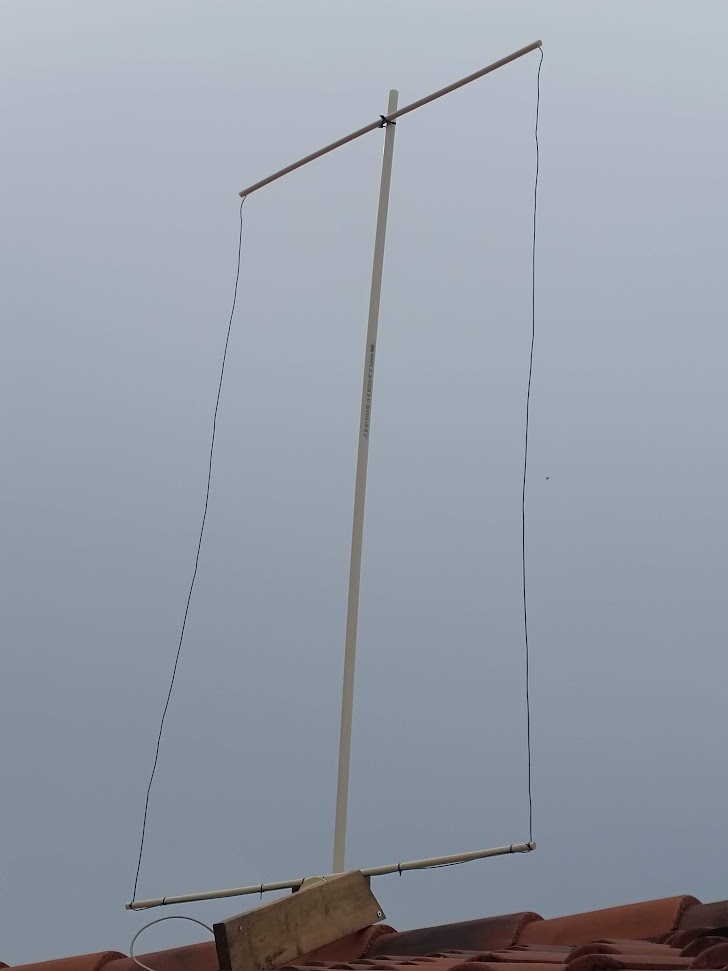
April 2024 I made a 50 MHz Oblong according to this.
Some pictures from building and mounting on roof:
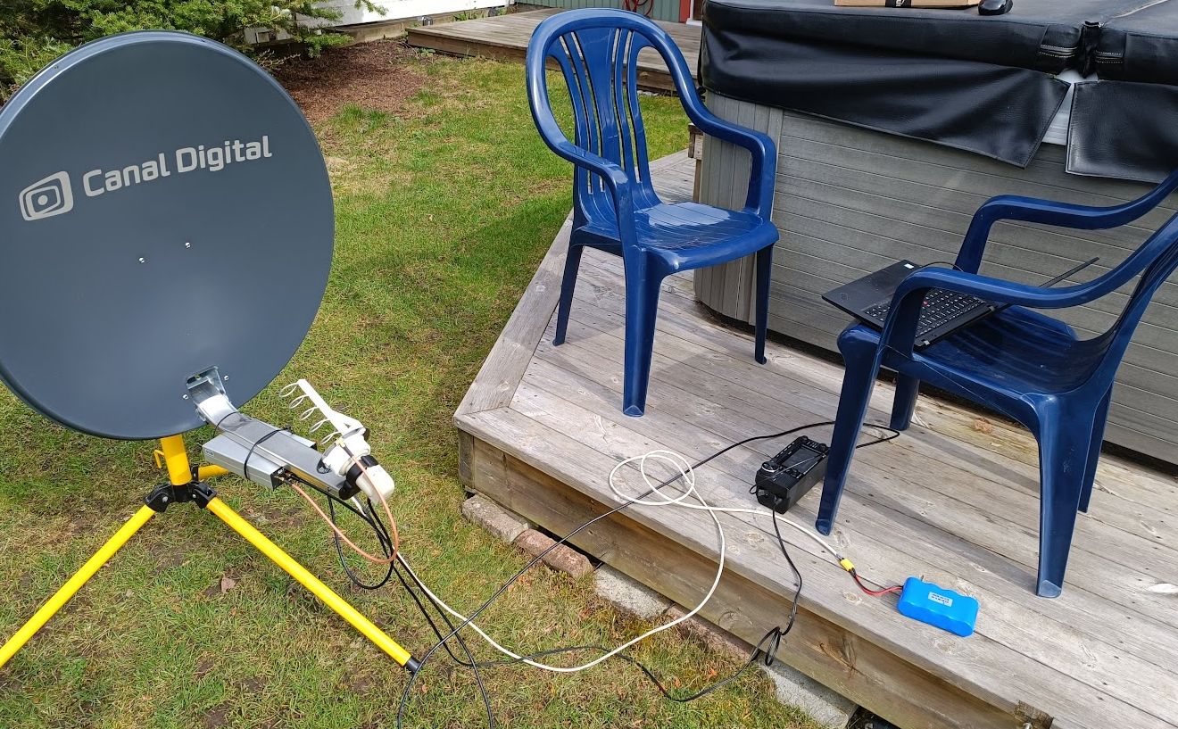
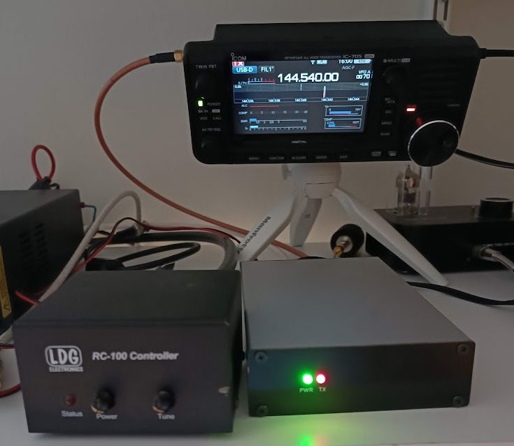
Today 12 April 2024 I made my first QO-100 QSOs via FT8 and FT4 with the SatRover transverter in the garden outside our house. I got a small pile-up!
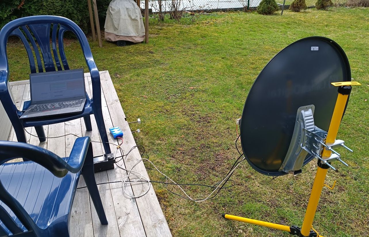
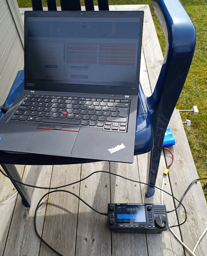
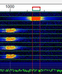
The first QO-100 RX test with SatRover and IC-705 the 22 mars 2024. What you see and here is the lower beacon.
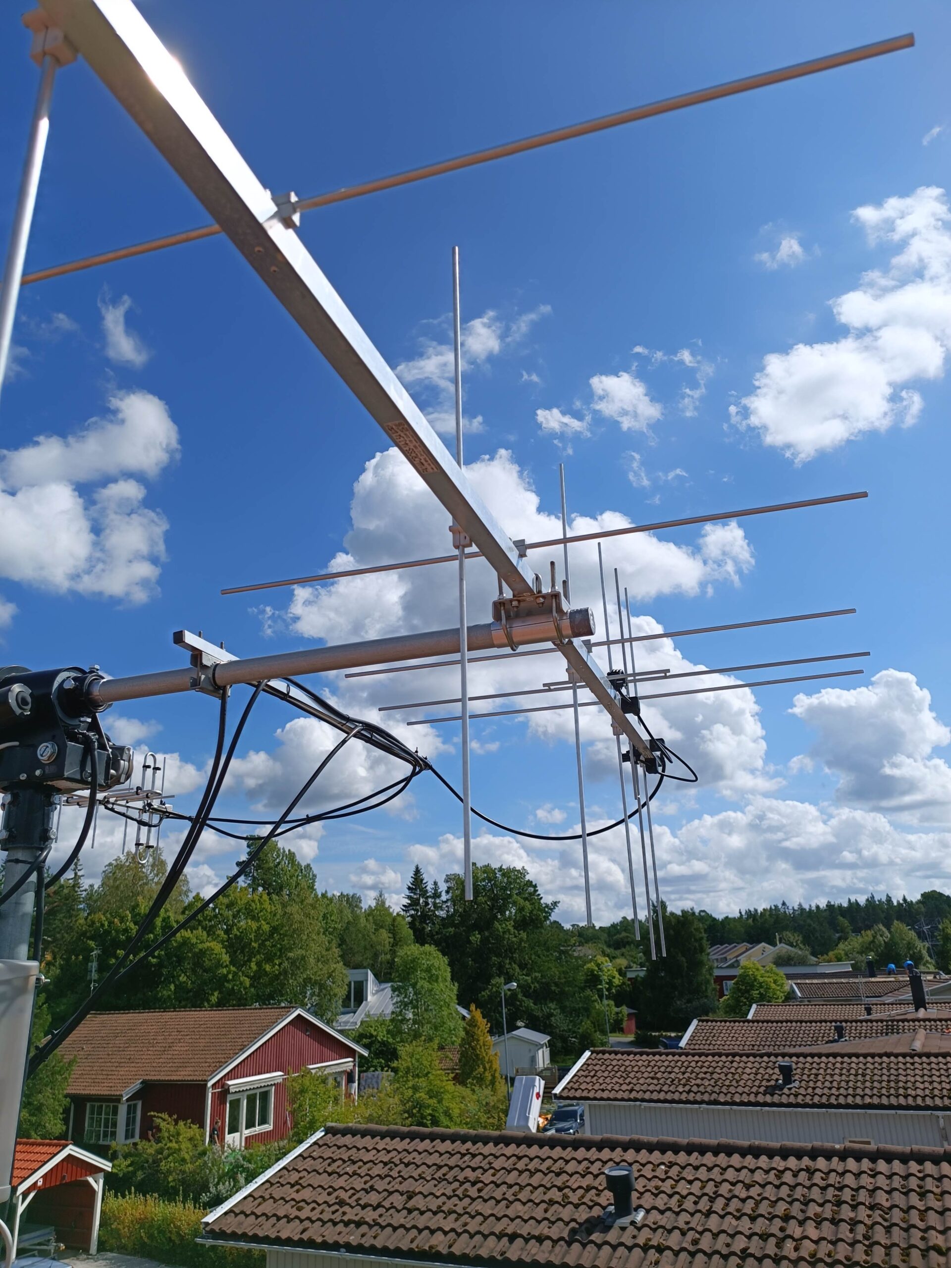
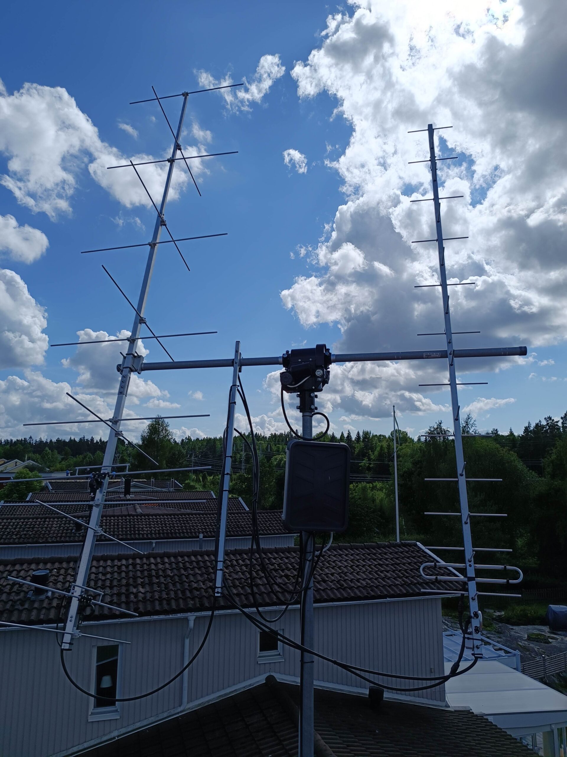
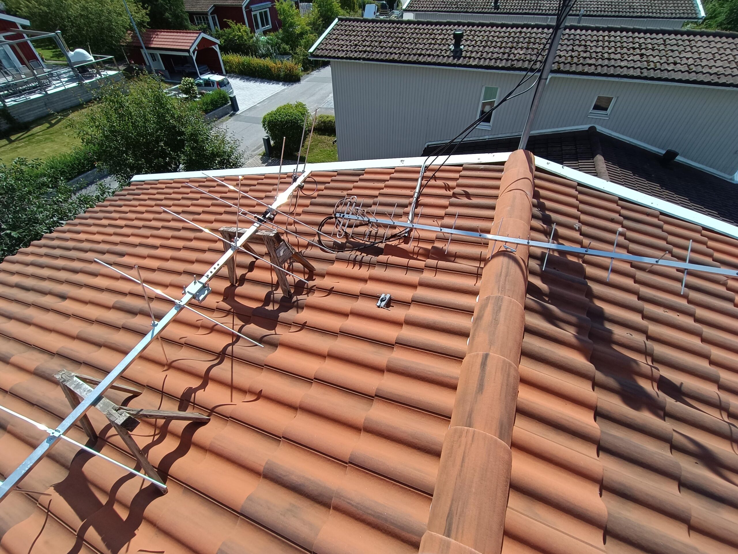
During August 2023 and removed my old GFK glasfiber tube and replaced with a new one – this one from Funk Elektronik.
Here are some pictures during the 3 hours of work…
First remove the antennas and the old tube:
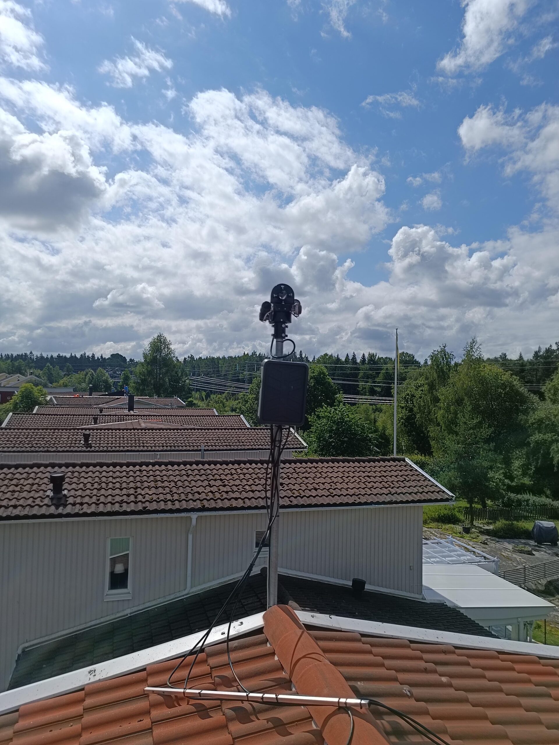
Then up with the new tube:
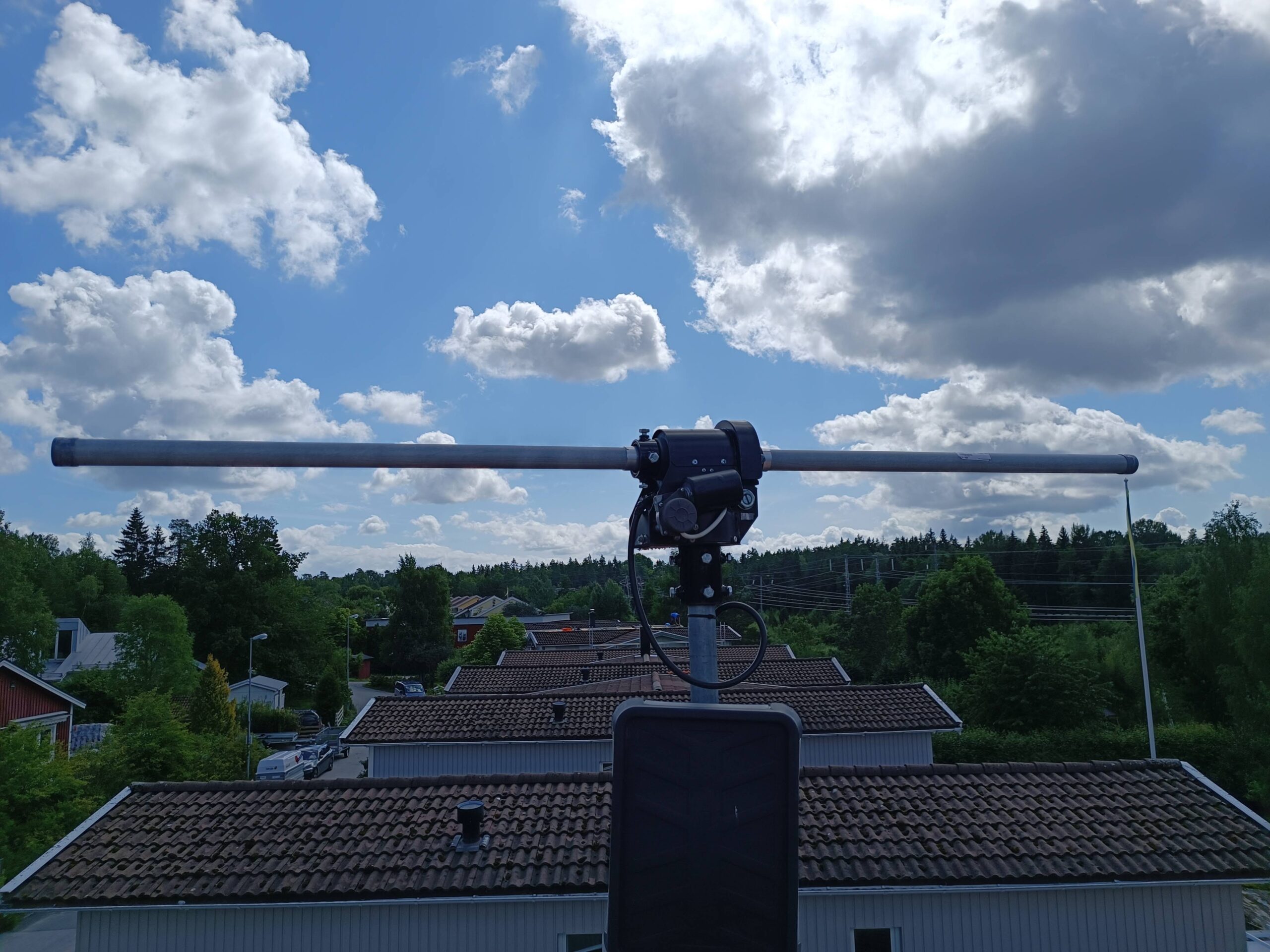
Then up with the antennas and support bom for cables. Here are several pictures from different angles: